
A hardware load balancer is a purpose-built physical appliance engineered with dedicated silicon, specialized network interfaces, and integrated cryptographic processors to distribute Layer 4 through Layer 7 traffic across server pools at line rate. Unlike commodity software routers that process packets via general-purpose operating system network stacks, these appliances decouple data forwarding from control management to sustain microsecond-level packet classification under full multi-hundred-gigabit line load.
When an enterprise network experiences ingress spikes exceeding 100 Gbps, standard x86 servers often buckle under soft interrupt storms, CPU cache thrashing, and context-switching penalties. Software network stacks relying on kernel space socket buffers introduce unpredictable latency jitter that degrades real-time applications such as high-frequency trading platforms, core banking systems, and large-scale media distribution fabrics.
Physical load-balancing appliances eliminate these bottlenecks by processing packets directly in hardware. By integrating Application-Specific Integrated Circuits (ASICs), Field-Programmable Gate Arrays (FPGAs), and Ternary Content-Addressable Memory (TCAM), physical appliances perform packet inspection, state tracking, and cryptographic termination without general-purpose CPU intervention.
Anatomy of a Hardware Load Balancer: ASICs, FPGAs, and Dedicated Silicon
At the physical layer, an enterprise hardware load balancer departs fundamentally from standard server architectures. While a commodity server routes network interrupts through PCIe buses to general-purpose x86 cores, a hardware based load balancer offloads the entire data plane onto custom silicon pipelines. This separation ensures that high packet rates do not starve management tasks or introduce non-deterministic processing delays.
+-----------------------------------------------------------------------+
| Physical Chassis Ingress Port |
| (100G / 400G QSFP28) |
+-----------------------------------+-----------------------------------+
 |
 v
+-----------------------------------------------------------------------+
| Network Interface & MAC Parser (PHY Layer) |
+-----------------------------------+-----------------------------------+
 |
 v
+-----------------------------------------------------------------------+
| Flow Classification Engine (ASIC / TCAM) |
| - Exact match L4 flow hashing (5-tuple lookup in single clock cycle)|
| - Access Control Lists & L4 DoS mitigation |
+-----------------+---------------------------------+-------------------+
 | |
 [Known L4 State / Fast Path] [New Flow / L7 Inspection]
 | |
 v v
+-----------------------------------+ +--------------------------------+
| Hardware Forwarding ASIC | | Hardware Crypto Engine (QAT) |
| - Line-rate NAT & SNAT rewrites | | - TLS handshake offloading |
| - MAC frame rewrite & egress queue| | - Bulk AES-GCM decryption |
+-----------------+-----------------+ +----------------+---------------+
 | |
 | v
 | +--------------------------------+
 | | High-Speed Control Plane CPU |
 | | - Complex L7 URL routing rules |
 | | - Dynamic health-check engine |
 | +----------------+---------------+
 | |
 +------------------+------------------+
 |
 v
+-----------------------------------------------------------------------+
| Chassis Egress Crossbar Switch |
+------------------------------------+----------------------------------+
 |
 v
+-----------------------------------------------------------------------+
| Physical Backend Server Pool |
+-----------------------------------------------------------------------+
The physical processing pipeline leverages distinct hardware components to achieve deterministic throughput:
- Custom ASICs: Hardwired silicon execution units optimized strictly for Ethernet frame parsing, IP checksum verification, Network Address Translation (NAT), and flow hashing. ASICs process standard Layer 4 packets within single clock cycles, sustaining sub-microsecond transit times.
- Ternary Content-Addressable Memory (TCAM): High-speed associative memory that evaluates complete access control lists, routing entries, and flow tables in parallel across the entire memory array in one clock cycle. Unlike RAM, which takes an address and returns data, TCAM takes data patterns and returns matches instantly.
- FPGAs: Reconfigurable silicon often deployed to run proprietary flow dispatching algorithms, packet filtering logic, or protocol modifications without necessitating tape-outs for new physical chips.
- Hardware Security Modules and Dedicated Crypto Engines: Discrete accelerator chips (such as Intel QuickAssist or proprietary vendor security processors) dedicated solely to asymmetric key operations (RSA/ECDSA) and bulk symmetric encryption (AES-GCM, ChaCha20-Poly1305).
Architecture Rule: A dedicated hardware load balancer isolates control planes (BGP peering, health check dispatching, configuration interfaces) from data planes (packet parsing, rewriting, forwarding). A control plane crash does not halt active packet forwarding along the ASIC data path.
| Hardware Component | Primary Functional Role | Processing Latency | Throughput Capability |
|---|---|---|---|
| Flow ASIC | L4 Parsing, 5-Tuple Hash, NAT | < 1 microsecond | Line rate (up to 800 Gbps) |
| TCAM | Parallel ACL & Policy Lookup | < 5 nanoseconds | Deterministic single-cycle search |
| FPGA Matrix | Dynamic Protocol Handling & Filtering | 1 to 3 microseconds | 100 Gbps to 400 Gbps |
| Crypto Processor | TLS Handshakes & Bulk Ciphers | 50 to 200 microseconds | Up to 150k handshakes/sec per card |
| x86 Control CPU | Health Checking, Orchestration, L7 | 10 to 500 milliseconds | Non-forwarding management plane |
Packet Flow Execution: Hardware SSL Acceleration and Kernel Bypass
Processing high-density traffic requires bypassing standard operating system layers that introduce latency. When a packet enters a physical appliance, it transitions through a deterministic sequence executed directly on the physical bus and silicon logic.
- Physical Ingress and MAC Parsing: The frame arrives on a high-density optical interface (such as a 100GbE QSFP28 port). The physical layer (PHY) deserializes the bitstream and passes the frame to the MAC parsing block of the flow ASIC.
- Hardware Flow Hashing and Session Lookup: The ASIC extracts the 5-tuple (source IP, destination IP, source port, destination port, IP protocol). It queries the TCAM table to determine if the packet matches an active connection state. If matched, it bypasses the central operating system entirely and executes the forwarding action directly.
- Cryptographic Offloading for Secure Traffic: If the packet represents a new TLS connection initiating a handshake, the ASIC directs the payload directly to the hardware cryptographic engine via dedicated PCIe DMA channels.
- Direct Memory Transfer to Isolated Processing Rings: In the event that Layer 7 content inspection (such as HTTP header transformation or cookie parsing) is required, the packet is moved to memory using zero-copy Direct Memory Access (DMA) rings. This mirrors kernel-bypass techniques such as DPDK, but runs over specialized memory interconnects designed for custom chassis backplanes.
- Session Persistence and Backend Dispatch: The persistence engine verifies source session affinities or cookie tables held in high-speed Static RAM (SRAM). The packet MAC and IP addresses are rewritten (SNAT/DNAT), CRC checksums are recomputed in silicon, and the frame is transmitted out the physical egress port.
Below is an architectural representation of how a dedicated hardware crypto engine unloads cryptographic routines from software pipelines using direct user-space acceleration primitives:
/* Conceptual representation of low-level hardware cryptographic accelerator pipeline */
#include <stdio.h>
#include <stdint.h>

struct tls_handshake_desc {
 uint32_t session_id;
 uint8_t client_random[32];
 uint8_t curve_type;
 uint16_t cipher_suite;
 void* hw_dma_buffer;
};

int dispatch_to_crypto_asic(struct tls_handshake_desc *packet) {
 /* Write packet descriptor pointer directly into memory-mapped I/O (MMIO) register */
 volatile uint32_t *crypto_engine_bar0 = (uint32_t *)0xF0008000;

 if (!packet ||!packet->hw_dma_buffer) {
 return -1; /* Hardware memory allocation error */
 }

 /* Trigger hardware ring-buffer pointer advancement without OS kernel intervention */
 *crypto_engine_bar0 = (uint32_t)(uintptr_t)packet->hw_dma_buffer;

 /* Asynchronous interrupt-free completion via hardware status polling bit */
 while ((*crypto_engine_bar0 & 0x1) == 0) {
 /* Hardware crypto accelerator processing ECDHE handshake computation */
 }

 return 0; /* Hardware accelerated handshake computed in single-digit microseconds */
}
Hardware vs Virtual Load Balancers: Architectural and Performance Trade-Offs
When deciding between a dedicated physical unit and a virtual load balancer, engineering teams must evaluate raw throughput limits against operational elasticity. A virtual appliance runs on a hypervisor (such as VMware ESXi, KVM, or AWS Nitro), sharing CPU, memory buses, and physical network interface cards with other workloads.
Shared virtualization abstractions introduce hypervisor context switching, CPU core scheduling contention, and I/O virtualization (SR-IOV) overhead. While software architectures can scale horizontally, individual virtual nodes exhibit higher tail latency (p99 and p99.9) under severe traffic bursts compared to dedicated hardware appliances with fixed processing pipelines.
| Metric / Capability | Dedicated Physical Appliance | Virtual Load Balancer (Hypervisor VM) | Software Bare-Metal (eBPF / DPDK) |
|---|---|---|---|
| L4 Packet Processing Latency | < 5 microseconds (deterministic) | 80 to 250 microseconds | 15 to 40 microseconds |
| L4 Throughput (Single Chassis/Node) | 100 Gbps to 1.6 Tbps | 10 Gbps to 40 Gbps | 40 Gbps to 100 Gbps |
| Layer 7 Requests Per Second | 2,000,000 to 15,000,000 | 50,000 to 400,000 | 500,000 to 2,500,000 |
| DDoS Syn-Flood Resistance | Hardware-rate drop (100M+ PPS) | Hypervisor vCPU saturation | 10M to 30M PPS (OS-dependent) |
| Deployment Velocity | Days/Weeks (Physical procurement) | Minutes (Infrastructure-as-Code) | Minutes (Container orchestration) |
| Hardware Refresh Cycle | 5 to 7 years | Decoupled from underlying hardware | Decoupled from underlying hardware |
Architects evaluating these models should apply the following deployment rubric:
- Deploy physical appliances when sustained line-rate traffic exceeds 100 Gbps per ingress point and predictable sub-millisecond p99 latency is non-negotiable.
- Deploy physical appliances when hardware-based cryptographic termination is needed to satisfy strict compliance isolation frameworks (such as FIPS 140-2 Level 3 physical HSM validation).
- Deploy virtual or software appliances when infrastructure requires programmatic scaling via Kubernetes operators or CI/CD pipelines.
- Deploy virtual options when operating in multi-cloud environments where physical appliance colocations are cost-prohibitive or physically impossible.
Resilience Architectures: Active-Active Pairs, VRRP, and BGP Anycast Routing
High availability in hardware topologies cannot rely on cloud-style auto-scaling groups. If a physical appliance fails, the surrounding network must divert traffic instantly without dropping active connection state tables. Physical deployments rely on three primary resilience strategies: Active-Passive high availability, Active-Active pairs with state mirroring, and BGP Anycast equal-cost multipath (ECMP) distribution.
Failover Reality: Active-Active pairs using traditional Layer 2 heartbeat synchronization (such as VRRP or CARP) suffer from scaling limits. Modern spine-leaf data centers prefer Layer 3 BGP Anycast, where multiple physical load balancers advertise the identical Virtual IP (VIP) address directly to Top-of-Rack (ToR) switches.
In a modern spine-leaf fabric, BGP Anycast distributes incoming ingress traffic across multiple physical units using ECMP routing hashes. If an appliance encounters an unrecoverable failure, its BGP daemon withdraws the host route advertisement, causing the upstream switches to recalculate hash buckets within milliseconds.
 +-----------------------+
 | Internet Gateway |
 +-----------+-----------+
 |
 +---------------+---------------+
 | |
 v v
 +-------------------+ +-------------------+
 | Spine Switch A | | Spine Switch B |
 +---------+---------+ +---------+---------+
 | \ / |
 | \ / |
 | \ / |
 v v v v
 +-------------------+ +-------------------+
 | Leaf Switch A | | Leaf Switch B |
 +---------+---------+ +---------+---------+
 | \ / |
 BGP VIP Match| \ / | BGP VIP Match
 198.51.100.1 | \ / | 198.51.100.1
 v v v v
 +-------------------+ +-------------------+
 | Hardware LB 01 |<=====>| Hardware LB 02 |
 | (Active Chassis) | Sync | (Active Chassis) |
 +---------+---------+ Link +---------+---------+
 | |
 +--------------+--------------+
 |
 v
 +-----------------------------+
 | Backend Server Pools (Rack)|
 +-----------------------------+
Below is a production-grade configuration snippet showing how an appliance announces a shared Virtual IP (198.51.100.1/32) to upstream Top-of-Rack BGP peers using BIRD routing software, incorporating physical link health checks:
# /etc/bird/bird.conf - BGP Anycast Route Advertisement for Hardware VIP
router id 10.0.0.1;

protocol device {
 scan time 2;
}

# Virtual IP interface defined on the appliance dummy interface
protocol direct {
 interface "dummy0";
}

# Health check script check: withdraw route if local load balancing engine degrades
protocol static vip_announcement {
 check link;
 route 198.51.100.1/32 via 10.0.0.1;
}

protocol bgp tor_switch_a {
 local as 64512;
 neighbor 10.0.0.2 as 64511;
 import none;
 export filter {
 if net = 198.51.100.1/32 then accept;
 reject;
 };
 connect retry time 5;
 hold time 15;
 keepalive time 5;
}

protocol bgp tor_switch_b {
 local as 64512;
 neighbor 10.0.0.3 as 64511;
 import none;
 export filter {
 if net = 198.51.100.1/32 then accept;
 reject;
 };
 connect retry time 5;
 hold time 15;
 keepalive time 5;
}
For session continuity during dynamic network reconvergence, physical appliances maintain a dedicated out-of-band serial or 10GbE point-to-point interconnect. This link continuously streams state-table deltas (TCP sequence numbers, client-cookie state, and TLS tickets) directly into the memory of the peer appliance, ensuring zero connection drops during maintenance transitions.
Five-Year TCO Evaluation: Power, Cabling, Refresh Cycles, and Cloud Interconnects
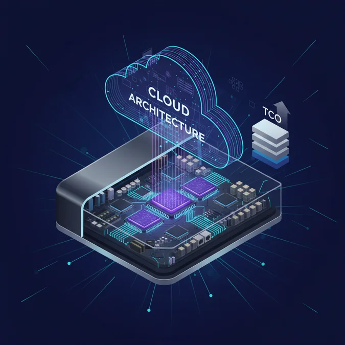
Calculating the true expenditure of enterprise physical network equipment extends well beyond the manufacturer retail price of the chassis. A rigorous Total Cost of Ownership (TCO) model must incorporate recurring operational expenditures across the equipment lifecycle, including high-density power draws, optical interconnects, support agreements, and end-of-life hardware refresh cadences.
| Cost Driver | Dedicated Physical Chassis Pair | Virtualized / Cloud-Native Software Instances |
|---|---|---|
| Initial Capital Expenditure | High (Chassis, ASICs, Crypto Modules, Optics) | Low to Zero (Commodity Compute / Cloud Subscriptions) |
| Datacenter Real Estate | 2U to 8U Rack Space per pair | Shared standard compute rack footprint |
| Power & Cooling Requirements | 750W to 2,400W continuous draw per chassis | Virtual allocation of host power budget |
| High-Speed Cabling | 40G/100G/400G Transceivers (SR4, LR4) & MPO fiber | Standard Cat6A or Twinax DAC cables |
| Vendor Maintenance & Support | Expensive mandatory hardware SLAs (RMA within 4 hours) | Tiered software enterprise license support |
| Scalability Cost Profile | Step-function cost curves (CapEx step at capacity limit) | Linear or dynamic utility pricing based on throughput |
| Obsolescence & Refresh | Complete hardware replacement every 5 to 7 years | Continuous rolling software updates and upgrades |
Engineering leadership should evaluate this operational checklist before committing to physical procurement:
- Confirm that existing datacenter racks supply sufficient dual-feed redundant power (A+B feeds) with C19/C20 plugs capable of sustaining peak chassis wattage.
- Calculate the total cost of optical transceivers. 100G QSFP28 and 400G QSFP-DD long-range transceivers can easily represent 20% to 30% of total hardware acquisition costs.
- Factor in 24/7/365 four-hour on-site replacement warranties. Without hardware replacement contracts, physical outages can halt mission-critical lines of business for days.
- Determine whether traffic egress costs over cloud interconnects (such as AWS Direct Connect or Azure ExpressRoute) negate the on-premises savings of running dedicated physical appliances.
Factors That Affect Development Cost
- Physical appliance throughput tier (10G vs 100G vs 400G)
- High-speed optical transceivers and cabling accessories
- Dedicated hardware cryptographic acceleration modules (FIPS HSMs)
- Continuous data center power consumption and cooling density
- Vendor 24/7/365 hardware replacement and software support contracts
Total costs vary widely depending on throughput capacities, redundant power requirements, and support tier levels.
Frequently Asked Questions
What is the core distinction between a hardware load balancer and a virtual load balancer?
A hardware load balancer runs on dedicated proprietary appliances with custom ASICs for line-rate packet switching, whereas a virtual load balancer runs as a software virtual machine on standard hypervisors, relying on shared host x86 CPU and memory resources.
When is a hardware based load balancer still preferred over software alternatives?
A hardware based load balancer is preferred in ultra-low latency trading, carrier-grade telecommunications, and high-density TLS offloading environments where deterministic microsecond response times and multi-hundred-gigabit sustained throughput exceed standard commodity x86 kernel capabilities.
Can software-defined networking replace a hardware load balancer entirely?
Software load balancers using DPDK and eBPF kernel bypass can match entry-level hardware appliances. However, enterprise hardware appliances remain unmatched for deterministic line-rate Layer 4 distribution without CPU jitter during extreme volumetric DDoS conditions.
How does hardware SSL termination improve backend server efficiency?
Hardware SSL termination offloads cryptographic handshakes and symmetric encryption to dedicated security processors on the appliance. This removes asymmetric mathematical overhead from backend application servers, preserving backend CPU cycles entirely for business logic execution.
Hardware load balancers remain foundational components for organizations running large-scale private datacenters, high-frequency trading platforms, and latency-critical telecommunications networks. Their custom silicon pipelines, integrated cryptographic engines, and TCAM lookups provide deterministic sub-microsecond packet routing and volumetric flood mitigation that general-purpose virtual appliances struggle to replicate at high line rates.
However, the modern engineering landscape requires balancing this peak raw performance against the agility, programmatic automation, and lower entry capital of cloud-native software load balancers. By understanding the structural trade-offs between physical ASICs, kernel-bypass drivers, and hypervisor virtualization, infrastructure architects can deploy the exact load balancing topology required for their throughput, latency, and operational constraints.