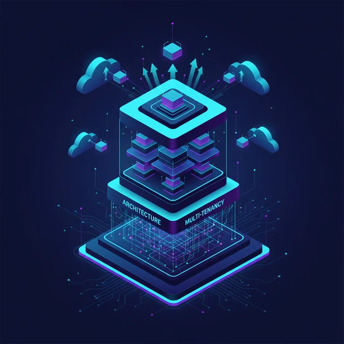

In software development, a pod refers either to a self-contained, multi-tenant deployment unit containing compute and data layers, an autonomous cross-functional engineering team, or the smallest schedulable compute unit in Kubernetes. In distributed architecture, a pod encapsulates a distinct tenant slice to isolate blast radiuses and optimize memory and database throughput.
With the release of Kubernetes 1.30 and modern cell-based cloud architectures, the pod concept has solidified into two fundamental engineering layers: infrastructure orchestration and multi-tenant partitioning. Designing applications around pod models requires balancing container boundary constraints, IPC mechanisms, shared volume semantics, and database sharding patterns.
This technical breakdown analyzes how pods function across container environments, distributed backend architectures, and engineering team topologies. We examine memory limits, Linux cgroups, shared kernel namespaces, state management trade-offs, and deployment pipelines using modern backend frameworks.
What Is a Pod in Software Engineering
A pod in software engineering represents a discrete, self-contained operational boundary. Depending on context, it designates an infrastructure compute primitive running co-located containers or an isolated architectural shard hosting end-to-end service dependencies for a dedicated partition of users. Both applications prioritize operational independence, predictable resource allocation, and zero side-effects across boundaries.
When evaluated in distributed backend systems, a pod bundles an isolated subset of application workers, asynchronous queue processors, ephemeral caches, and transactional databases. This architectural isolation ensures that catastrophic failures, such as unbounded query loops or runaway worker memory allocations, remain bounded within a single tenant group.
Architectural Taxonomies of Pods
- Infrastructure Primitive: An atomic scheduling envelope grouping multiple Linux containers that share networking namespaces, IPC mechanisms, and storage volumes.
- Architectural Cell: A self-sufficient, multi-tenant deployment island housing web nodes, database replicas, and cache instances dedicated to a fixed user cohort.
- Organizational Pod: A cross-functional engineering squad (containing product, frontend, backend, and QA engineers) maintaining single-domain autonomy over distinct operational pods.
Understanding the clear boundary between infrastructure primitives and architectural cells prevents structural anti-patterns, such as attempting to run monolithic database engines directly inside transient orchestrator pods without persistent volume abstractions.
Kubernetes Pod Architecture and Container Primitives
At the infrastructure level, a Kubernetes pod acts as the fundamental compute unit. Rather than managing isolated containers, the orchestrator schedules pods as atomic allocations onto cluster worker nodes. All containers packaged within a single pod execute within shared Linux namespaces, giving them joint access to a virtual network interface, local loopback addressing, and shared inter-process communication channels.
The foundational container inside every Kubernetes pod is the pause container. When the kubelet instantiates a pod, it first starts the pause container, which reserves and retains the underlying Linux kernel namespaces: net, ipc, uts, and optionally pid.
apiVersion: v1
kind: Pod
metadata:
 name: worker-pod
 labels:
 app.kubernetes.io/name: telemetry-ingestion
spec:
 shareProcessNamespace: true
 containers:
 - name: ingestion-service
 image: registry.internal/telemetry/ingestion:v2.4.1
 resources:
 limits:
 memory: "512Mi"
 cpu: "1000m"
 requests:
 memory: "256Mi"
 cpu: "250m"
 ports:
 - containerPort: 8080
 name: http-metrics
 - name: log-shipper-sidecar
 image: registry.internal/telemetry/shipper:v1.1.0
 resources:
 limits:
 memory: "128Mi"
 cpu: "100m"
 requests:
 memory: "64Mi"
 cpu: "50m"
In this deployment, setting shareProcessNamespace: true allows the auxiliary sidecar container to inspect and coordinate with processes running inside the primary application container. When architecting systems, engineers working alongside a hardware and firmware team frequently leverage these namespace isolation techniques to bridge raw hardware telemetry feeds into standardized containerized networks.
Process Isolation, cgroups, and Memory Management
Container isolation within a pod relies on Linux Control Groups (cgroups v2) to enforce strict boundary accounting on CPU, memory, I/O, and swap utilization. When multiple containers execute within one pod, their resource quotas are aggregated at the pod cgroup level, while individual container constraints dictate local process eviction behavior.
Memory exhaustion leads directly to kernel Out-Of-Memory (OOM) score evaluation. When a container exceeds its defined limits.memory, the Linux kernel invokes oom-killer to terminate processes within that container without necessarily shutting down the parent pod unless marked non-restartable.
| Metric | cgroups v1 Implementation | cgroups v2 Modern Standard | Operational Impact |
|---|---|---|---|
| Memory Controller | Fragmented files (memory.limit_in_bytes) | Unified hierarchy (memory.max, memory.high) | Enables proactive throttling before harsh SIGKILL |
| I/O Attribution | Buffered writes attributed incorrectly | Accurate writeback I/O tracking per cgroup | Eliminates silent disk starvation between containers |
| PSI Metrics | Unavailable | Pressure Stall Information natively exposed | Allows proactive horizontal pod autoscaling on I/O stall |
| Resource Nesting | Arbitrary independent controller hierarchies | Unified single root tree structure | Ensures child container limits cleanly subdivide pod limits |
To ensure high database connection and compute reliability, backend engineers must ensure that runtime process heaps (such as PHP OPcache or Node.js V8 isolates) remain safely below the memory.max ceiling, preventing unexpected cascading restarts under heavy traffic surges.
Pod Networking, Localhost Loopback, and IPC
A defining characteristic of the infrastructure pod is its network homogeneity. Every container inside a pod shares the identical network namespace, IP address, and port space assigned by the Container Network Interface (CNI) plugin. Containers communicate with each other using the localhost loopback interface.
This arrangement drastically cuts network transport latency compared to multi-node HTTP RPC. Sidecars can intercept incoming traffic, validate mutual TLS (mTLS), or write metrics to co-located processes through UNIX domain sockets mounted to an ephemeral emptyDir volume.
# Inspecting the shared network namespace across two containers in pod
$ lsns -t net
 NS TYPE NPROCS PID USER NETNSID NSFS
4026532488 net 4 1248 root 0 /proc/1248/ns/net

# Verifying active ports visible identically in both containers
$ ss -tulpn
Netid State Recv-Q Send-Q Local Address:Port Peer Address:Port
tcp LISTEN 0 128 127.0.0.1:6379 0.0.0.0:*
tcp LISTEN 0 511 0.0.0.0:8080 0.0.0.0:*
Because port conflicts cause runtime initialization failures, two distinct containers in the same pod cannot bind to the identical TCP port. Ports must be managed systematically across the primary application, telemetry log forwarders, and reverse proxies.
Multi-Container Pod Design Patterns
Composing multiple containers within an infrastructure pod requires disciplined architectural patterns. Containers must maintain a unified lifecycle, failing and scaling together. Three primary design patterns dominate distributed systems engineering: Sidecar, Ambassador, and Adapter.
1. Sidecar Pattern
The sidecar pattern attaches an auxiliary task to enhance the core application container without mutating its codebase. Common sidecar implementations include runtime log collection, configuration reloaders watching external key-value stores, and database connection pooling brokers.
2. Ambassador Pattern
The ambassador pattern abstracts outbound network topologies. The application container connects to localhost, while the ambassador container handles complex routing, circuit breaking, retry budgets, and dynamic service discovery.
3. Adapter Pattern
The adapter pattern normalizes heterogeneous payloads and interfaces. If legacy microservices emit inconsistent monitoring telemetry, an adapter sidecar reformats local traces into OpenTelemetry-compliant endpoints for unified collector scraping.
These patterns work effectively when decoupling concerns, but developers must account for pod startup race conditions. In native Kubernetes, init containers execute sequentially to completion before application containers start, preventing early traffic routing to uninitialized endpoints.
Pod-Based Architectural Cells in Distributed Systems
Beyond orchestrator primitives, high-throughput software architectures define a pod as an independent, fully isolated deployment cell. Rather than maintaining a single global database and compute fleet serving millions of users, the application footprint is fractured into discrete, self-sustaining pods.
In this pattern, each architectural pod contains its own API gateways, compute workers, message queues, and dedicated database instances. A shared routing tier (often called a Cell Router) maps incoming requests to their designated pod based on tenant IDs, regional boundaries, or cryptographic hashes.
Architectural Pod Isolation Mechanics
- Blast Radius Containment: A database corruption bug or bad code deployment deployed to Pod 4 affects only the tenants assigned to Pod 4, leaving Pods 1 through 3 entirely unaffected.
- Bypassing Database Scaling Ceilings: Relational databases hit connection and write throughput bottlenecks at scale. By bounding each pod to 50,000 active accounts, database limits are never tested by total platform growth.
- Deterministic Performance: High-traffic noisy neighbors are placed in isolated compute-heavy pods, ensuring consistent query latency for standard accounts.
Cell-based pods require robust data placement and directory services to ensure that cross-pod dependencies are eliminated. Distributed transactions across multiple architectural pods must be strictly avoided to prevent distributed deadlocks.
Implementing Multi-Tenant Pods in Backend Frameworks
Deploying distributed cell architectures requires rigorous context binding within application code. In modern web frameworks, this means intercepting incoming HTTP requests, extracting tenant partition keys, and dynamically bootstrapping database connections and cache prefixes corresponding to that specific pod.
Consider an enterprise backend written in modern PHP. A middleware inspects incoming traffic, dynamically resolving which isolated tenant shard must execute the request. This eliminates cross-tenant data leakage while ensuring transactional boundaries remain isolated to the designated data store.
<php

declare(strict_types=1);

namespace App\Http\Middleware;

use Closure;
use Illuminate\Http\Request;
use Illuminate\Support\Facades\Config;
use Illuminate\Support\Facades\DB;
use Symfony\Component\HttpFoundation\Response;

final class TenantPodRoutingMiddleware
{
 public function handle(Request $request, Closure $next): Response
 {
 $tenantIdentifier = $request->header(\'X-Tenant-ID\');

 if (!$tenantIdentifier ||!is_string($tenantIdentifier)) {
 return response()->json([\'error\' => \'Missing or invalid tenant identifier\'], 400);
 }

 // Resolve specific pod database credentials from isolated memory lookup
 $podConfig = $this->resolvePodConfiguration($tenantIdentifier);

 Config:set(\'database.connections.tenant_pod\', [
 \'driver\' => \'pgsql\',
 \'host\' => $podConfig[\'host\'],
 \'database\' => $podConfig[\'database\'],
 \'username\' => $podConfig[\'username\'],
 \'password\' => $podConfig[\'password\'],
 \'charset\' => \'utf8\',
 \'prefix\' => \'\',
 \'schema\' => \'public\',
 ]);

 // Purge old instance to force reconnect under new isolated tenant scope
 DB:purge(\'tenant_pod\');
 DB:reconnect(\'tenant_pod\');

 return $next($request);
 }

 private function resolvePodConfiguration(string $tenantId): array
 {
 // Deterministic routing lookup or internal cluster directory query
 return [
 \'host\' => sprintf(\'pod-%s-db.internal\', substr(hash(\'sha256\', $tenantId), 0, 8)),
 \'database\' => \'tenant_app\',
 \'username\' => \'pod_worker\',
 \'password\' => env(\'POD_DB_SECRET\'),
 ];
 }
}
When handling high-volume operational events across these pods, such as event-driven communications, teams must pair dynamic routing with decoupled messaging patterns. Implementing a robust messaging broker ensures that asynchronous dispatches remain reliable, as detailed in our analysis of scalable notification system design.
State Management and Data Persistence Across Pods
Handling persistence within pods presents severe engineering challenges. Infrastructure pods are intrinsically ephemeral: nodes fail, clusters autoscale, and schedulers evict pods during upgrades. Architectural pods, conversely, host durable application state that cannot be discarded.
To reconcile these opposing properties, systems utilize abstracted volume lifecycle models. Kubernetes isolates block storage from container runtimes via PersistentVolumes (PV) backed by CSI drivers, while architectural pods utilize read-write-many object stores or sharded distributed database nodes.
| Storage Pattern | Access Mode | Latency Profile | Primary Engineering Trade-off |
|---|---|---|---|
| emptyDir | ReadWriteOnce (Local Node) | Sub-millisecond (RAM/Disk) | Data is destroyed immediately when the pod is deleted or evicted |
| PersistentVolume (EBS/Ceph) | ReadWriteOnce (Network Block) | 2 to 8 milliseconds | Volume attachment serialization delays pod restart during node migration |
| Distributed File System (NFS/EFS) | ReadWriteMany (Shared Network) | 10 to 50 milliseconds | Severe file locking bottlenecks under concurrent high-throughput workloads |
| Cell-Local Database Node | TCP Direct Shard Connection | Sub-millisecond to 2 ms | Requires global directory service to map tenant queries to correct pod shard |
Architects must treat infrastructure pods as compute-only workers whenever possible, offloading persistent mutations to managed database clusters or local stateful sets designed specifically with write-ahead log (WAL) durability guarantees.
Organizational Engineering Pods: Structure and Metrics
In software development methodologies, the term pod also describes an organizational unit: a small, autonomous, cross-functional team assembled to deliver continuous value over a dedicated problem space. Popularized by agile delivery models, an organizational pod operates with minimal inter-team handoffs.
A typical software pod contains four to eight specialists: one Product Owner, one Tech Lead, two to four Backend and Frontend Engineers, a QA Automation Engineer, and a designated Site Reliability Engineer. This structure shifts accountability entirely to the pod, allowing teams to own both the code and the deployment pipelines for their microservices.
Key Operational Metrics for Engineering Pods
- Deployment Frequency (DORA): How often the pod deploys code to staging and production environments autonomously without external gating approvals.
- Change Failure Rate (CFR): The percentage of deployments originating from the pod that require hotfixes, rollbacks, or lead to production incidents.
- Mean Time to Restore (MTTR): The elapsed time between an incident occurrence within the pod service scope and full production restoration.
- Service Level Objectives (SLOs): Uptime, error rate thresholds, and p99 request latency benchmarks defined for services owned directly by the pod.
Organizational pods mirror Conway Law: teams organized around isolated technical pods produce decoupled, cell-based software architectures with well-defined API boundaries.
Monitoring, Observability, and Health Probes in Pod Deployments
Observability within pod environments requires multi-layered instrumentation. Because infrastructure pods can fail silently while process threads remain running, container platforms mandate precise health checking protocols: Startup, Liveness, and Readiness probes.
A common misconfiguration is configuring liveness probes that query deep transactional databases. If the downstream database stutters, all application pods fail their liveness probes simultaneously, initiating a catastrophic cluster-wide cascading restart. Probes must evaluate only local container readiness.
livenessProbe:
 httpGet:
 path: /healthz/liveness
 port: 8080
 initialDelaySeconds: 10
 periodSeconds: 5
 timeoutSeconds: 2
 failureThreshold: 3
readinessProbe:
 httpGet:
 path: /healthz/readiness
 port: 8080
 initialDelaySeconds: 5
 periodSeconds: 3
 timeoutSeconds: 2
 failureThreshold: 2
In this configuration, if the readinessProbe fails, the orchestrator immediately strips the pod IP from active load balancer endpoints without terminating the process, preventing failed requests while allowing in-flight buffers to drain naturally.
At the distributed cell level, observability demands tenant-aware tracing. Every request header must carry an immutable trace ID and tenant ID across HTTP, gRPC, and queue boundaries. Log aggregators use these tags to filter operational telemetry down to a single degraded pod instance.
Security Implications and Attack Surface Hardening
Because containers in an infrastructure pod share memory namespaces, IPC resources, and network stacks, an exploit inside one vulnerable container directly compromises the perimeter of adjacent sidecars. Hardening the pod runtime boundary is non-negotiable in production systems.
By default, containers execute without explicit user namespace remapping, meaning UID 0 inside a container can map directly to UID 0 on the host kernel if container runtimes fail to enforce security profiles. Applying strict security contexts mitigates this attack vector completely.
spec:
 securityContext:
 runAsNonRoot: true
 runAsUser: 10001
 runAsGroup: 10001
 fsGroup: 10001
 seccompProfile:
 type: RuntimeDefault
 containers:
 - name: secure-api
 image: registry.internal/core/api:v3.1.0
 securityContext:
 allowPrivilegeEscalation: false
 readOnlyRootFilesystem: true
 capabilities:
 drop:
 - ALL
Enforcing a readOnlyRootFilesystem prevents compromised processes from downloading executable payloads to /tmp or altering system shared libraries. Any temporary scratch space required by the service must be mounted as an ephemeral in-memory medium with execution flags disabled.
Architectural Directory and Further Reading
Mastering decoupled runtime primitives, container orchestration, and multi-tenant partitioning patterns forms the foundation of modern high-availability web engineering.
Explore our complete Laravel, Basics directory for more guides.
Frequently Asked Questions
What is the difference between a pod and a container?
A container is a single sandboxed process running inside isolated Linux namespaces and cgroups. A pod is an orchestrator wrapper that groups one or more containers together, enabling them to share the same network namespace, IP address, storage volumes, and lifecycle.
Why would a pod have multiple containers?
Pods use multiple containers to implement helper patterns like sidecars, ambassadors, or adapters. These secondary containers handle auxiliary concerns like log rotation, metrics scraping, dynamic secret fetching, or reverse proxy caching without coupling that code to the primary application.
What is an architectural pod in distributed systems?
An architectural pod (or cell) is a self-contained, independent slice of an entire platform. It contains its own application compute, caching, and database instances to serve a specific cohort of users, strictly limiting the system blast radius during hardware or software failures.
What is a software development team pod?
An organizational software pod is a small, autonomous, cross-functional team typically consisting of four to eight members. It includes engineers, product owners, and QA specialists who take complete end-to-end ownership over a specific business domain and its associated microservices.
Whether deployed as an infrastructure execution unit inside Kubernetes or implemented as an autonomous cell to isolate multi-tenant workloads, the pod pattern establishes clear operational boundaries. By bounding networking, memory management, and blast radiuses to discrete units, distributed systems achieve higher fault tolerance and predictable scaling curves.
Designing effective pod architectures requires deliberate trade-offs: balancing the simplicity of monolithic deployments against the governance overhead of automated cell routing, storage attachments, and namespace security. Implementing these patterns methodically ensures applications scale horizontally without sacrificing stability or operational visibility.